Welchen Neigungsmesserausgang oder welche serielle Schnittstelle sollten Sie wählen?
All inclinometers and tilt sensors measure a change in the effect of gravitational field on a mass to derive angle. As the
inclinometer sensor is rotated, the sensing element is subject to gravitational forces which move the proof mass.
The signal generated by this movement is measured, and through a digital signal processor the response is
linearised and sent to an output interface. The data collected can then be logged, viewed in various graphical forms or be tracked over certain time periods.
With high-speed data so common today, it is easy to get lost in the plethora of serial interfaces available to allow connection of an inclinometer to a compatible device via a single path of data transmission. However, inclinometers are generally used in applications where large distances exceeding several feet are required and therefore Analogue, RS232 or RS485 interfaces are the most commonly used. Each has their own advantages, disadvantages and affinity for different applications. At Level Developments, both Analogue output devices (range between 4 – 20mA) and Digital output devices (RS232, RS485 and RS485-Modbus) are available, but which one is right for you?
Analogue Outputs
Inclinometers with analogue 4–20 mA current loops contain two values of 4 & 20 mA representing 0–100% of the range of measurement or control. These loops are commonly used for electronic signalling, both for carrying sensor information from field instrumentation, such as tilt angle, and carrying control signals to relevant device. Inclinometers with analogue 0.5V – 9.5V also contain two sensing elements mounted perpendicular to one another so that the device can measure both the X and Y axis simultaneously. Internally these two sensors are measured and a processor derives the angular position. This angle is then converted to a voltage which is linear with the change in angle. In this device there are two output voltage stages, one for each of the measurement axis. As the angle is varied over the full scale range the output voltage changes between 0.5 to 4.5V or 0.5 to 9.5V depending on the product option.
Analogue inclinometers are relatively popular and easily accessible due to their high compatibility with other devices. Furthermore, they can be run over long distances with minimal signal loss and have low electromagnetic and noise susceptibility due to their rugged signals. However, they do have a high power consumption and are usually slower to transfer data compared to digital interfaces. Analogue applications include the monitoring of remote equipment over long distances.
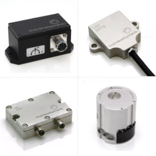
Product ranges with analogue outputs by Level Developments include: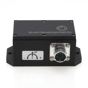
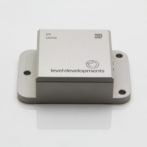
- VS Series
- LSOC Series
Digital Outputs
RS232
RS232 is a digital output type that is also common on inclinometers as RS232 COM ports have been widely available on personal computers since they were first invented to connect printers and other external devices. RS232 serial devices are also compatible with universal asynchronous receiver transmitter (UART) cables and a number of additional readily available components. The main disadvantage of the RS232 output is that it is limited to small cable lengths, and therefore low data rates if longer cable lengths are desired. This is especially true in comparison to RS485 outputs (See below), where the cable length can reach up to 1200m as opposed to just 15m with RS232 outputs, depending on the baud rate. However, this does make RS232 outputs generally more affordable in comparison. Its applications are usually restricted to low distance requirements with low data transmission.
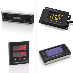
Product ranges with RS232 outputs by Level Developments include:
- VS Series
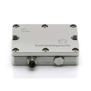
- HPS Series
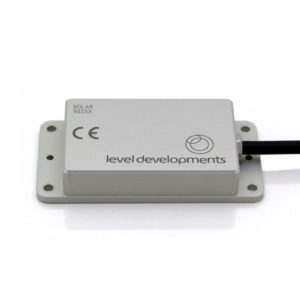
- SOLAR Series
- SUBSEA Series
- LCH-45
- LCH-360
- LCP-45
RS485
RS485 is another digital output type, although able to use both full and half-duplex signals as opposed to just full duplex signals on the RS232. It is more modern than RS232 (38 years newer, in fact), meaning that it is very popular in modern systems and can hugely outperform RS232 protocols when distance is a factor as it is able to transmit signals over extremely long distances at higher rates. Another significant difference is that it allows up to 128 sensors on 1 single network, known as multi-drop, since sensors contain individual addresses and so can be distinguished on the network. Additionally, RS485 is less susceptible to electrical noise and therefore less likely to have corrupted data.
However, it does come with drawbacks as the RS485 output type is not widely available on computers since it is not commonplace on more commercial devices. There are, however, many inexpensive and widely available USB adapters online that can accommodate this output type. RS485 is also compatible with UART and other components, as well as Modbus interfaces.
RS485-Modbus
The RS485-Modbus output is not too dissimilar to that of the RS485, also citing cable length, transmission rates and transmit distance as key strengths, whilst the lack of compatible devices is a weakness. However, Modbus protocols allow more control over transmission and configuration. In regular RS485 transmission, a master/slave framework is utilised, where the master acts as the transmitter and sends a request to a specified slave, acting as the receiver. The master waits for a response and if not received in a specified time-frame, will terminate the communication.
With a Modbus interface, the master has the choice of addressing messages to designated slave devices, or communicating with them all at once using a special “Broadcast” address. This can only be initiated by the master, starting with the slave ID being sent either to accept a query or inform the master which device supplied the reply. Each slave is attached to the bus in parallel with a unique slave ID. Its applications are best suited to those where multiple sensors need to be connected to one interface and controlled simultaneously.
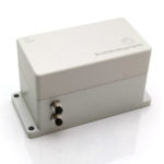
For both RS485 outputs, product ranges by Level Developments include: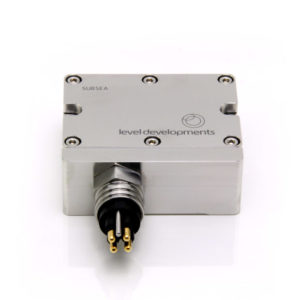
- HPS series
- SOLAR Series
- SUBSEA Series
Other
At Level Developments, we also supply additional output interfaces that may not be as common for inclinometers. USB outputs are usually used for applications with very short distances (< 3m), although they have relatively quick speeds. J1939CAN is a two-wire, half duplex, high-speed network system used in applications where real-time readings are required due to its high transfer speeds. Inclinometers with J1939CAN interfaces are usually designed for use with industrial, agricultural and construction machinery as they are considered to be very safe and reliable. Cable lengths tend to be under 40 meters.
TCP/IP Modbus protocols uses TCP/IP and Ethernet to carry the data of the Modbus message structure between compatible devices. The inclinometer acts as a server, while the The PC or PLC acts as the client. The client needs to open a valid TCP/IP socket with the device before communication can take place by using the inclinometer’s IP address. Using byte commands, the device can then be read and written. It is usually used for its superiority in transporting large amounts of data and the fact that there is an unlimited amount of devices that can be connected to the network. Its cable length can reach up to 1000m. The following products contain these outputs: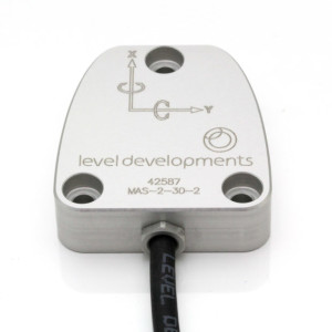
- DCL Series (CAN J1939)
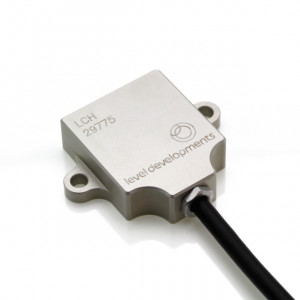
- LCH Series (USB)
- MAS Series (TCP/IP)
Summary
In Summary, the output type you should choose is entirely dependent on its application. For general applications where shorter distances and smaller amounts of data are being transferred in one direction at a time, an RS232 output is most suitable. If longer distances are required, and speed of transmission is not vital, an analogue interface would be appropriate. For applications where longer distances, higher speeds and larger amounts of data are being transmitted, an RS485 output would be best suited, particularly if multiple sensors need to be connected. The same is true for an RS485-Modbus protocol, which should be considered if there needs to be more control over the configuration of multiple sensors or they need to be programmed together, as well as if data needs to be both transmitted and received simultaneously. Other output types such as USB should be used for short distance and low data applications, whilst J1939CAN should be used where quick data transfer and real-time readings are required; and TCP/IP Modbus will usually be used when large amounts of data are being transmitted and a large number of devices need to be connected to the network.